
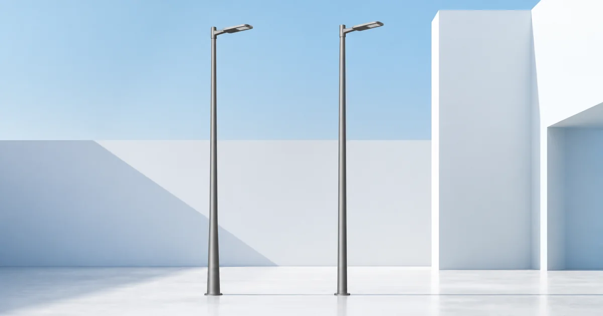
Round tapered and round straight aluminum light poles are both widely used for exterior lighting, but they solve different visual and coordination needs. The right choice is not a matter of one profile being universally better. It depends on the project’s mounting height, luminaire and bracket arrangement, wind criteria, foundation interface, finish, installation method and architectural intent.
This guide gives buyers, designers and contractors a practical way to compare the two shapes without turning a catalog image into an engineering claim. For a broader overview of available shafts and configurations, visit our aluminum light pole range. If your project requires a tapered shaft, review the aluminum tapered light pole page as well.
1. Start with the project brief
Write down the luminaire model, total projected area, mounting arrangement, pole height, site location, design wind speed, exposure category, base condition and required finish. A useful comparison does not begin with a preferred silhouette. It begins with the loads the completed assembly must resist and the details a contractor must install.
For this comparison, document the condition in writing and have the responsible project team review it before production. Small changes in equipment, attachment location, exposure or anchorage can change the appropriate configuration. A manufacturer can prepare a more useful proposal when the brief is complete, the assumptions are visible and the drawing is treated as the controlling record.
2. Compare the shaft profiles
A round tapered shaft reduces diameter from base to top. A round straight shaft keeps a constant outside diameter over most of its length. Both can be engineered for outdoor lighting, but their proportions, available mounting space and visual effect are different. Neither profile is automatically stronger without the governing design inputs.
For this comparison, document the condition in writing and have the responsible project team review it before production. Small changes in equipment, attachment location, exposure or anchorage can change the appropriate configuration. A manufacturer can prepare a more useful proposal when the brief is complete, the assumptions are visible and the drawing is treated as the controlling record.
3. Choose the tapered profile when height matters
Tapered poles are often selected for roadway, parking, campus and area-lighting layouts where a taller, lighter-looking shaft is helpful. The narrowing upper section can create a clean visual transition to the luminaire. Final wall and base dimensions still have to be selected for the actual wind, fixture and arm configuration.
For this comparison, document the condition in writing and have the responsible project team review it before production. Small changes in equipment, attachment location, exposure or anchorage can change the appropriate configuration. A manufacturer can prepare a more useful proposal when the brief is complete, the assumptions are visible and the drawing is treated as the controlling record.
4. Choose the straight profile when consistency matters
Straight round poles are commonly considered where a uniform architectural appearance, repeated accessory mounting position or a matching existing family is important. The constant diameter can also make the visual language easy to repeat along pedestrian routes, plazas and low-rise commercial properties.
For this comparison, document the condition in writing and have the responsible project team review it before production. Small changes in equipment, attachment location, exposure or anchorage can change the appropriate configuration. A manufacturer can prepare a more useful proposal when the brief is complete, the assumptions are visible and the drawing is treated as the controlling record.
5. Separate appearance from structural selection
A photograph can show profile preference, but it cannot establish structural adequacy. A pole quotation should identify height, shaft geometry, material and temper, wall schedule, top and bottom dimensions, arm or tenon details, base plate, anchor-bolt pattern and the wind assumptions used for selection.
For this comparison, document the condition in writing and have the responsible project team review it before production. Small changes in equipment, attachment location, exposure or anchorage can change the appropriate configuration. A manufacturer can prepare a more useful proposal when the brief is complete, the assumptions are visible and the drawing is treated as the controlling record.
6. Define the lighting package
Ask for the luminaire weight, effective projected area, side-mounted accessory area, top mounting method and centre of gravity. Decorative housings, cameras, banners, brackets and arms can materially change the governing load. A generic pole recommendation is not a substitute for the real equipment data.
For this comparison, document the condition in writing and have the responsible project team review it before production. Small changes in equipment, attachment location, exposure or anchorage can change the appropriate configuration. A manufacturer can prepare a more useful proposal when the brief is complete, the assumptions are visible and the drawing is treated as the controlling record.
7. Account for mounting height
The bending demand at the base rises with height and with the lever arm of a side-mounted fixture. Two poles with the same profile can require very different dimensions when one supports a short post-top luminaire and the other supports an outreach arm with a larger fixture.
For this comparison, document the condition in writing and have the responsible project team review it before production. Small changes in equipment, attachment location, exposure or anchorage can change the appropriate configuration. A manufacturer can prepare a more useful proposal when the brief is complete, the assumptions are visible and the drawing is treated as the controlling record.
8. Review arms and drilling early
Single arms, double arms, side drill holes, handholes and other openings should be determined before fabrication. These details affect local reinforcement, orientation, delivery documentation and installation. Provide a drawing that shows the arm direction, number of fixtures and required rotational alignment.
For this comparison, document the condition in writing and have the responsible project team review it before production. Small changes in equipment, attachment location, exposure or anchorage can change the appropriate configuration. A manufacturer can prepare a more useful proposal when the brief is complete, the assumptions are visible and the drawing is treated as the controlling record.
9. Use wind criteria consistently
Wind design is project-specific. The location, exposure, terrain, local code, attachment EPA and mounting configuration must be applied as one system. Do not compare a tapered and straight option whose assumptions are different; otherwise apparent price or weight differences are meaningless.
For this comparison, document the condition in writing and have the responsible project team review it before production. Small changes in equipment, attachment location, exposure or anchorage can change the appropriate configuration. A manufacturer can prepare a more useful proposal when the brief is complete, the assumptions are visible and the drawing is treated as the controlling record.
10. Include the foundation and anchors
A pole is only one part of the installed assembly. Base plate, bolt circle, anchor bolt grade and projection, foundation geometry, concrete condition and soil information may govern installation. Confirm who is responsible for the foundation design and whether local engineering review is required.
For this comparison, document the condition in writing and have the responsible project team review it before production. Small changes in equipment, attachment location, exposure or anchorage can change the appropriate configuration. A manufacturer can prepare a more useful proposal when the brief is complete, the assumptions are visible and the drawing is treated as the controlling record.
11. Consider aluminum material and finish
For aluminum poles, alloy and temper, surface finish and project environment should be stated clearly. Mill finish, anodized and powder-coated options have different visual and maintenance considerations. Coastal, industrial and high-humidity locations should be assessed before a finish is selected.
For this comparison, document the condition in writing and have the responsible project team review it before production. Small changes in equipment, attachment location, exposure or anchorage can change the appropriate configuration. A manufacturer can prepare a more useful proposal when the brief is complete, the assumptions are visible and the drawing is treated as the controlling record.
12. Think about transportation and handling
Length, diameter, packaged accessories and loading method influence freight and site handling. A tapered shaft can have a different nesting or visual handling profile from a straight shaft, but shipment planning must be based on actual dimensions, quantities and destination constraints.
For this comparison, document the condition in writing and have the responsible project team review it before production. Small changes in equipment, attachment location, exposure or anchorage can change the appropriate configuration. A manufacturer can prepare a more useful proposal when the brief is complete, the assumptions are visible and the drawing is treated as the controlling record.
13. Plan luminaire interface details
Tenon size, slip-fitter requirement, top cap, drilling orientation and wire routing need to match the selected luminaire. A clean transition at the top of the shaft improves both appearance and installation efficiency. Ask the luminaire supplier for dimensional drawings rather than relying on product photographs.
For this comparison, document the condition in writing and have the responsible project team review it before production. Small changes in equipment, attachment location, exposure or anchorage can change the appropriate configuration. A manufacturer can prepare a more useful proposal when the brief is complete, the assumptions are visible and the drawing is treated as the controlling record.
14. Coordinate inspection access
Handhole location, grounding provision, wireway access and any internal components should be checked against the installer’s requirements. Their positions must also be coordinated with arm orientation and base access. This is a small drawing-stage decision that can prevent an on-site rework.
For this comparison, document the condition in writing and have the responsible project team review it before production. Small changes in equipment, attachment location, exposure or anchorage can change the appropriate configuration. A manufacturer can prepare a more useful proposal when the brief is complete, the assumptions are visible and the drawing is treated as the controlling record.
15. Check site context
Tapered poles often suit open roads, car parks and campus approaches, while straight shafts can suit repeated architectural rhythms. This is an aesthetic tendency, not a structural rule. Existing streetscape, fixture form, spacing and sightlines should guide the visual choice after engineering inputs are defined.
For this comparison, document the condition in writing and have the responsible project team review it before production. Small changes in equipment, attachment location, exposure or anchorage can change the appropriate configuration. A manufacturer can prepare a more useful proposal when the brief is complete, the assumptions are visible and the drawing is treated as the controlling record.
16. Avoid catalogue-only comparisons
Catalogue dimensions are useful starting points, but they do not confirm compatibility with a particular luminaire and wind zone. Compare like for like: same height, same attachments, same wind criteria, same finish scope, same anchorage assumption and the same delivery terms.
For this comparison, document the condition in writing and have the responsible project team review it before production. Small changes in equipment, attachment location, exposure or anchorage can change the appropriate configuration. A manufacturer can prepare a more useful proposal when the brief is complete, the assumptions are visible and the drawing is treated as the controlling record.
17. Use a drawing approval process
Before release, review a dimensional drawing covering pole profile, height, base, bolt circle, handhole, arms, top detail, material, finish and quantity. Mark any site-specific orientation requirements. This approval record is more reliable than a description copied from an earlier project.
For this comparison, document the condition in writing and have the responsible project team review it before production. Small changes in equipment, attachment location, exposure or anchorage can change the appropriate configuration. A manufacturer can prepare a more useful proposal when the brief is complete, the assumptions are visible and the drawing is treated as the controlling record.
18. Request transparent quotations
A useful quotation separates the pole, arms, tenons, anchors, finish, packing, freight and engineering or testing scope where applicable. It should also name any information still required from the buyer. That clarity makes tapered and straight options easier to evaluate without hidden scope differences.
For this comparison, document the condition in writing and have the responsible project team review it before production. Small changes in equipment, attachment location, exposure or anchorage can change the appropriate configuration. A manufacturer can prepare a more useful proposal when the brief is complete, the assumptions are visible and the drawing is treated as the controlling record.
19. Install with the approved documents
Use the manufacturer’s installation instructions, approved anchor layout and local safety practice. Protect finished surfaces during handling, align the pole before final tightening and coordinate wiring with a qualified installer. Do not field-drill or modify a structural shaft without written review.
For this comparison, document the condition in writing and have the responsible project team review it before production. Small changes in equipment, attachment location, exposure or anchorage can change the appropriate configuration. A manufacturer can prepare a more useful proposal when the brief is complete, the assumptions are visible and the drawing is treated as the controlling record.
20. Maintain the completed installation
Periodically inspect coatings, fasteners, doors, arms, luminaires and signs of impact or corrosion. Keep maintenance records and address damage early. The selected profile does not remove the need for routine inspection; it simply forms one part of a designed lighting assembly.
For this comparison, document the condition in writing and have the responsible project team review it before production. Small changes in equipment, attachment location, exposure or anchorage can change the appropriate configuration. A manufacturer can prepare a more useful proposal when the brief is complete, the assumptions are visible and the drawing is treated as the controlling record.
21. Make the final choice
Select round tapered when the visual taper and height-oriented appearance support the project, and select round straight when a uniform cylindrical profile better fits the site or equipment plan. In both cases, base the decision on a documented load brief and approved drawing rather than a profile name alone.
For this comparison, document the condition in writing and have the responsible project team review it before production. Small changes in equipment, attachment location, exposure or anchorage can change the appropriate configuration. A manufacturer can prepare a more useful proposal when the brief is complete, the assumptions are visible and the drawing is treated as the controlling record.
Frequently asked questions
Is a tapered pole always lighter?
Not necessarily. Weight depends on the approved geometry, wall schedule, height, accessories and structural design requirements. Compare final drawings and scope, not profile names.
Can either profile use a side arm?
Both may be configured for compatible mounting arrangements when the engineering and fabrication details are specified. Provide fixture, arm and wind data early.
Which profile is better for wind?
Neither profile can be selected from appearance alone. Use the project wind criteria and attachment information; see our light pole wind load calculation guide for the information typically needed.
Next step
Send the pole height, fixture drawing, effective projected area, mounting method, location, wind criteria, finish preference and foundation information. We can help translate that brief into a round tapered or round straight aluminum light pole configuration with a drawing-ready scope.