
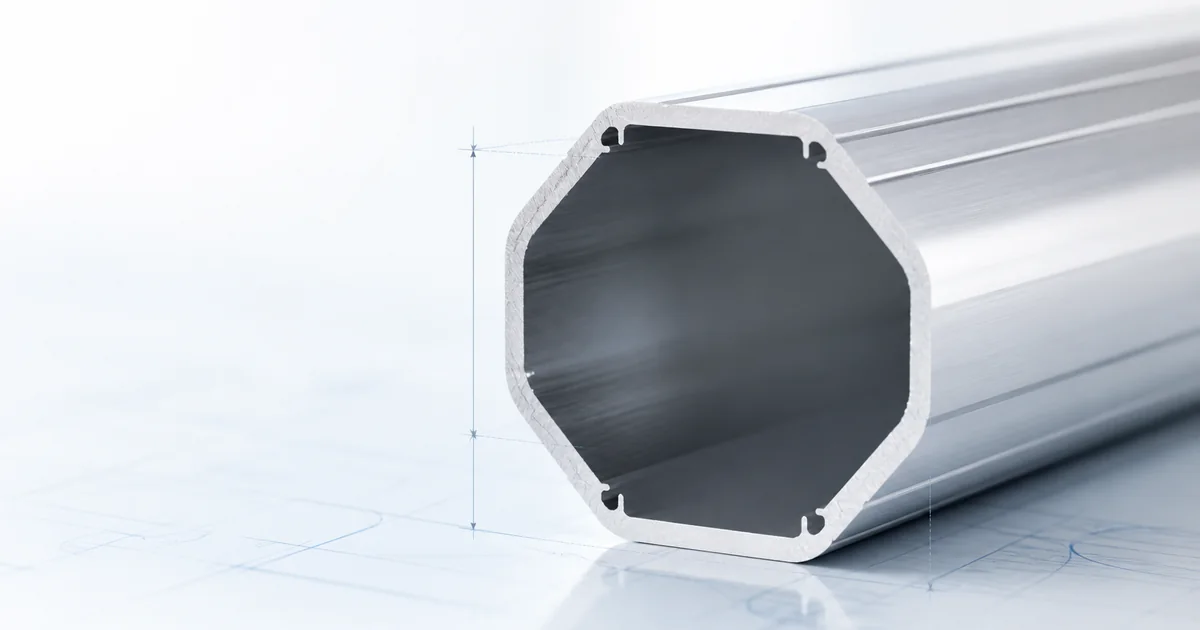
Wall thickness is one of the most requested specifications for an aluminum light pole, yet it is often treated as if it alone decides strength or service life. It does not. A suitable pole is an engineered assembly in which shaft geometry, material, temper, mounting height, fixture effective projected area, arm design, wind criteria, anchorage and foundation work together. This guide explains how to discuss wall thickness intelligently when purchasing or specifying custom aluminum lighting poles.
Quick answer
Do not choose an aluminum pole wall thickness from height alone. First define the fixture arrangement, mounting height, effective projected area, project wind criteria and anchorage. Then request a drawing that identifies the complete shaft and installation system. For a material overview, read our 6063-T6 aluminum light pole guide.
1. Wall thickness is a system property
Wall thickness contributes to section capacity, local stiffness and the way an extruded shaft behaves around connections. It is therefore recorded together with the shaft profile, butt diameter, top diameter, height and alloy-temper designation. A number quoted without those related dimensions is not a complete engineering specification. Selection should be based on documented project information and reviewed against the applicable design requirements. Ask the manufacturer to state the assumptions used, because values that appear comparable can rely on different wind conditions, attachment layouts or anchorage details. A clear drawing gives the purchaser, installer and design team a common reference and reduces the risk of selecting an aluminum light pole by one isolated number.
2. Start with the application
A decorative pedestrian installation, a roadway assembly and a parking-area pole can look similar at a distance but experience different load combinations. Define the lighting purpose, mounting height, fixture count, arm arrangement and future accessories before asking for a wall thickness recommendation. Selection should be based on documented project information and reviewed against the applicable design requirements. Ask the manufacturer to state the assumptions used, because values that appear comparable can rely on different wind conditions, attachment layouts or anchorage details. A clear drawing gives the purchaser, installer and design team a common reference and reduces the risk of selecting an aluminum light pole by one isolated number.
3. Understand the load path
Wind acting on the luminaire and arm is transmitted through the top connection, shaft, base or embedded portion, anchorage and foundation. The shaft is only one part of that path. A thicker shaft does not correct inadequate anchor bolts, unsuitable embedment or an attachment arrangement outside the approved design. Selection should be based on documented project information and reviewed against the applicable design requirements. Ask the manufacturer to state the assumptions used, because values that appear comparable can rely on different wind conditions, attachment layouts or anchorage details. A clear drawing gives the purchaser, installer and design team a common reference and reduces the risk of selecting an aluminum light pole by one isolated number.
4. Consider the alloy and temper
For many extruded round aluminum pole applications, 6063-T6 is selected because it supports extrusion, finishing and appropriate mechanical properties. The material designation should be confirmed on the approved drawing; it should not be inferred only from an appearance or a supplier’s general description. Selection should be based on documented project information and reviewed against the applicable design requirements. Ask the manufacturer to state the assumptions used, because values that appear comparable can rely on different wind conditions, attachment layouts or anchorage details. A clear drawing gives the purchaser, installer and design team a common reference and reduces the risk of selecting an aluminum light pole by one isolated number.
5. Height changes the demand
As height increases, the lever arm from the applied wind load to the base generally increases. A configuration that works at one mounting height cannot be assumed to work at a greater height merely by retaining the same wall thickness. Geometry and attachment details must be reviewed together. Selection should be based on documented project information and reviewed against the applicable design requirements. Ask the manufacturer to state the assumptions used, because values that appear comparable can rely on different wind conditions, attachment layouts or anchorage details. A clear drawing gives the purchaser, installer and design team a common reference and reduces the risk of selecting an aluminum light pole by one isolated number.
6. Fixture EPA is essential
The effective projected area of the luminaire, arm and accessories affects wind demand. Two fixtures with similar weight can have very different EPA values. Use the fixture cut sheet and include every attachment when requesting a project-specific aluminum pole configuration. Selection should be based on documented project information and reviewed against the applicable design requirements. Ask the manufacturer to state the assumptions used, because values that appear comparable can rely on different wind conditions, attachment layouts or anchorage details. A clear drawing gives the purchaser, installer and design team a common reference and reduces the risk of selecting an aluminum light pole by one isolated number.
7. Arms affect more than aesthetics
A straight tenon, short arm, davit arm and double-arm layout create different force paths. Outreach can introduce bending and torsion, while multiple arms can change the governing wind case. Specify the arm geometry and orientation rather than referring only to a general pole family. Selection should be based on documented project information and reviewed against the applicable design requirements. Ask the manufacturer to state the assumptions used, because values that appear comparable can rely on different wind conditions, attachment layouts or anchorage details. A clear drawing gives the purchaser, installer and design team a common reference and reduces the risk of selecting an aluminum light pole by one isolated number.
8. Round tapered shaft geometry
A tapered aluminum shaft changes diameter along its length. That geometry affects appearance, material distribution and structural behavior. The wall specification is meaningful only when paired with the stated taper, butt diameter, top diameter and mounting height shown on the product drawing. Selection should be based on documented project information and reviewed against the applicable design requirements. Ask the manufacturer to state the assumptions used, because values that appear comparable can rely on different wind conditions, attachment layouts or anchorage details. A clear drawing gives the purchaser, installer and design team a common reference and reduces the risk of selecting an aluminum light pole by one isolated number.
9. Round straight shaft geometry
A straight-round shaft uses a more uniform visual profile. It may suit certain architectural layouts and accessory arrangements, but it still requires a project-specific review. Compare actual dimensions and design inputs rather than assuming a straight profile requires more or less thickness than a tapered profile. Selection should be based on documented project information and reviewed against the applicable design requirements. Ask the manufacturer to state the assumptions used, because values that appear comparable can rely on different wind conditions, attachment layouts or anchorage details. A clear drawing gives the purchaser, installer and design team a common reference and reduces the risk of selecting an aluminum light pole by one isolated number.
10. Square shaft geometry
Square aluminum poles may be selected for contemporary commercial and pedestrian environments. Their flat faces, corner details and accessory interfaces need to be considered with the design load. Wall thickness is one input among the dimensions and connection details of the complete square shaft. Selection should be based on documented project information and reviewed against the applicable design requirements. Ask the manufacturer to state the assumptions used, because values that appear comparable can rely on different wind conditions, attachment layouts or anchorage details. A clear drawing gives the purchaser, installer and design team a common reference and reduces the risk of selecting an aluminum light pole by one isolated number.
11. Anchor-base installation
Anchor-base systems transfer load through a base plate, anchor bolts and concrete foundation. Bolt pattern, base geometry, concrete, reinforcement and site conditions affect performance. The pole drawing and foundation design must be coordinated; neither should be selected from an unrelated project. Selection should be based on documented project information and reviewed against the applicable design requirements. Ask the manufacturer to state the assumptions used, because values that appear comparable can rely on different wind conditions, attachment layouts or anchorage details. A clear drawing gives the purchaser, installer and design team a common reference and reduces the risk of selecting an aluminum light pole by one isolated number.
12. Direct-burial installation
Direct-burial poles require appropriate embedment, soil assumptions, drainage and corrosion-aware detailing. The below-grade portion is part of the design. A comparison with an anchor-base pole cannot be made from wall thickness alone because the installation mechanisms are different. Selection should be based on documented project information and reviewed against the applicable design requirements. Ask the manufacturer to state the assumptions used, because values that appear comparable can rely on different wind conditions, attachment layouts or anchorage details. A clear drawing gives the purchaser, installer and design team a common reference and reduces the risk of selecting an aluminum light pole by one isolated number.
13. Connection details
Handholes, wiring access, arm connections, tenons and base details are local features that may require specific treatment. Their design must be considered in the approved assembly. Avoid drilling additional holes or fitting unapproved attachments in the field without confirming their effect. Selection should be based on documented project information and reviewed against the applicable design requirements. Ask the manufacturer to state the assumptions used, because values that appear comparable can rely on different wind conditions, attachment layouts or anchorage details. A clear drawing gives the purchaser, installer and design team a common reference and reduces the risk of selecting an aluminum light pole by one isolated number.
14. Finish and environmental exposure
Anodized and powder-coated finishes can support appearance and durability, but they do not replace sound structural selection. In coastal or industrial environments, drainage, compatible fasteners, isolation of dissimilar metals and maintenance access should be addressed as part of the complete specification. Selection should be based on documented project information and reviewed against the applicable design requirements. Ask the manufacturer to state the assumptions used, because values that appear comparable can rely on different wind conditions, attachment layouts or anchorage details. A clear drawing gives the purchaser, installer and design team a common reference and reduces the risk of selecting an aluminum light pole by one isolated number.
15. Weight, transport and erection
A thicker wall can increase pole weight. That can influence lifting equipment, manual handling, shipping and installation planning. These practical effects should be considered after the design criteria have been established, not used as a reason to omit required structural checks. Selection should be based on documented project information and reviewed against the applicable design requirements. Ask the manufacturer to state the assumptions used, because values that appear comparable can rely on different wind conditions, attachment layouts or anchorage details. A clear drawing gives the purchaser, installer and design team a common reference and reduces the risk of selecting an aluminum light pole by one isolated number.
16. Catalog data and custom work
Catalog options are useful for concept selection and budgeting. They are not a substitute for the actual project schedule of fixtures, wind criteria, arms and anchorage. Where a standard size does not fit the design, a custom aluminum pole drawing can establish the required configuration. Selection should be based on documented project information and reviewed against the applicable design requirements. Ask the manufacturer to state the assumptions used, because values that appear comparable can rely on different wind conditions, attachment layouts or anchorage details. A clear drawing gives the purchaser, installer and design team a common reference and reduces the risk of selecting an aluminum light pole by one isolated number.
17. Quotation comparison
Compare quotations line by line: alloy and temper, shaft dimensions, wall thickness, pole height, arm type, finish, anchorage, fixture assumptions and included accessories. A lower price may reflect different assumptions rather than an equivalent pole system. Selection should be based on documented project information and reviewed against the applicable design requirements. Ask the manufacturer to state the assumptions used, because values that appear comparable can rely on different wind conditions, attachment layouts or anchorage details. A clear drawing gives the purchaser, installer and design team a common reference and reduces the risk of selecting an aluminum light pole by one isolated number.
18. Documentation before production
The approved drawing should record the dimensions and assumptions that control the product. It should identify the mounting arrangement, attachment requirements, access openings, base or embedment details, finish and project reference. This helps prevent later changes from invalidating the original selection. Selection should be based on documented project information and reviewed against the applicable design requirements. Ask the manufacturer to state the assumptions used, because values that appear comparable can rely on different wind conditions, attachment layouts or anchorage details. A clear drawing gives the purchaser, installer and design team a common reference and reduces the risk of selecting an aluminum light pole by one isolated number.
19. Installation controls
Inspect delivered poles against the approved drawing, use the specified lifting points and protect the finish during handling. Confirm that the foundation, anchors or embedment work match the intended configuration before erection. Field modifications should be reviewed rather than treated as routine. Selection should be based on documented project information and reviewed against the applicable design requirements. Ask the manufacturer to state the assumptions used, because values that appear comparable can rely on different wind conditions, attachment layouts or anchorage details. A clear drawing gives the purchaser, installer and design team a common reference and reduces the risk of selecting an aluminum light pole by one isolated number.
20. Maintenance and future changes
Periodic inspection can identify coating damage, loose accessories, drainage issues and unapproved additions. If fixtures are upgraded, banners are added or arms are changed, review the pole system again. The original wall thickness was selected for a documented assembly, not for unlimited future loading. Selection should be based on documented project information and reviewed against the applicable design requirements. Ask the manufacturer to state the assumptions used, because values that appear comparable can rely on different wind conditions, attachment layouts or anchorage details. A clear drawing gives the purchaser, installer and design team a common reference and reduces the risk of selecting an aluminum light pole by one isolated number.
How to request the right configuration
Send the proposed location, mounting height, fixture cut sheet, arm layout, EPA, finish requirement and anchorage preference. If the project requires a direct-burial installation, include available soil and embedment information. If it uses an anchor base, coordinate the foundation and anchor-bolt requirements with the responsible project team. For mounting-method context, see direct burial versus anchor base poles.
Frequently asked questions
Does a thicker wall always mean a better pole?
No. It may change the shaft properties and weight, but the correct configuration depends on the whole assembly and design criteria.
Can I select wall thickness from a competitor’s catalog?
Use catalog information only as a starting point. Confirm that height, wind criteria, fixture EPA, arm geometry and anchorage assumptions are equivalent.
Where can I find aluminum pole options?
Explore our custom aluminum light pole range and share your project details for a suitable drawing.
Conclusion
Wall thickness belongs in the final drawing, not at the beginning of an assumption. By documenting the complete lighting assembly and site requirements, buyers can compare aluminum poles accurately and obtain a configuration that suits the intended project.