
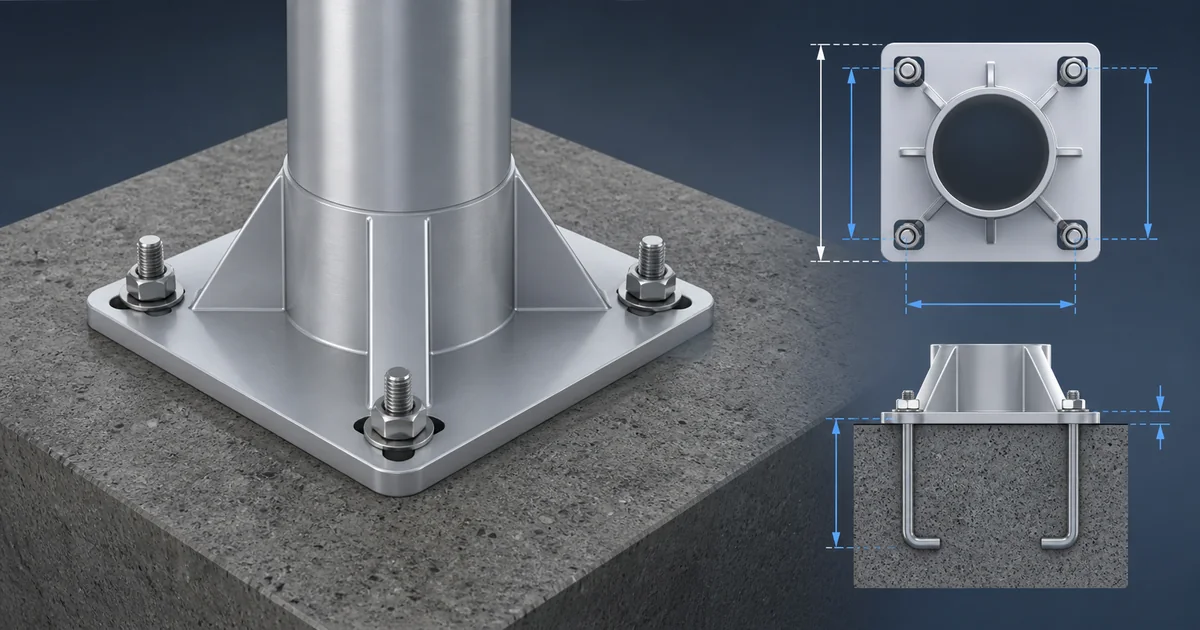
An aluminum light pole anchor-bolt pattern is a key connection between the pole base and the foundation. It affects installation accuracy, structural coordination, access orientation and the ability to replace or maintain a pole later. The right pattern cannot be chosen from pole height alone: it must match the approved pole, attachments, wind criteria and foundation design.
This guide explains the information buyers, designers and contractors should collect before ordering an anchor-base aluminum pole. For configurable shaft options, visit our aluminum light pole range.
1. What an anchor-bolt pattern defines
An anchor-bolt pattern is the coordinated set of bolt quantity, diameter, grade, bolt circle, projection, template and base-plate holes used to connect an anchor-base pole to its foundation. It is not a generic accessory. The pattern must match the approved pole base and foundation design.
Document this item in the project brief and review it with the responsible design and installation team. The purpose is not to impose a one-size-fits-all detail, but to ensure that the pole, anchor bolts and foundation are coordinated as one installed system. Project conditions, local codes and approved drawings remain controlling.
2. Start with the approved pole configuration
Before selecting bolts, confirm pole height, shaft geometry, luminaire weight, fixture EPA, arms, brackets, access-door orientation, finish and wind criteria. A change to any of these can alter base reactions and the appropriate connection. Use the approved pole drawing as the controlling reference.
Document this item in the project brief and review it with the responsible design and installation team. The purpose is not to impose a one-size-fits-all detail, but to ensure that the pole, anchor bolts and foundation are coordinated as one installed system. Project conditions, local codes and approved drawings remain controlling.
3. Understand bolt circle and base plate
The bolt circle is the diameter passing through the centers of the anchor bolts. Base plate dimensions and hole locations are designed together with it. A similar-looking base plate cannot be assumed compatible; measure from the approved drawing and use the specified template during foundation work.
Document this item in the project brief and review it with the responsible design and installation team. The purpose is not to impose a one-size-fits-all detail, but to ensure that the pole, anchor bolts and foundation are coordinated as one installed system. Project conditions, local codes and approved drawings remain controlling.
4. Do not select bolt diameter from pole height alone
A taller pole often has greater overturning demand, but height is only one input. The actual wind criteria, attachment projected area, arm reach, shaft dimensions and foundation arrangement must be assessed together. Bolt diameter, embedded length and grade belong to the designed assembly.
Document this item in the project brief and review it with the responsible design and installation team. The purpose is not to impose a one-size-fits-all detail, but to ensure that the pole, anchor bolts and foundation are coordinated as one installed system. Project conditions, local codes and approved drawings remain controlling.
5. Coordinate wind and attachment data
A post-top luminaire, a single outreach arm and a double-arm road fixture load the base differently. Obtain the luminaire drawing, weight, effective projected area and mounting center. For a useful project input checklist, read our light pole wind load calculation guide.
Document this item in the project brief and review it with the responsible design and installation team. The purpose is not to impose a one-size-fits-all detail, but to ensure that the pole, anchor bolts and foundation are coordinated as one installed system. Project conditions, local codes and approved drawings remain controlling.
6. Confirm the foundation responsibility
Pole manufacturers, civil engineers, contractors and project owners may have different responsibilities. Establish who designs the foundation, verifies soil assumptions and approves the anchor-bolt layout. A pole drawing does not automatically replace local foundation design or permitting requirements.
Document this item in the project brief and review it with the responsible design and installation team. The purpose is not to impose a one-size-fits-all detail, but to ensure that the pole, anchor bolts and foundation are coordinated as one installed system. Project conditions, local codes and approved drawings remain controlling.
7. Use the correct anchor template
The template keeps bolt locations, spacing and orientation accurate while concrete is placed. It should match the bolt circle and hole pattern on the approved base plate. Check the template before the pour, then protect exposed threads and verify projection before installation.
Document this item in the project brief and review it with the responsible design and installation team. The purpose is not to impose a one-size-fits-all detail, but to ensure that the pole, anchor bolts and foundation are coordinated as one installed system. Project conditions, local codes and approved drawings remain controlling.
8. Check projection and leveling
Anchor bolts require sufficient projection for the base plate, washers and nuts, with adjustment allowance as stated in the design. Leveling nuts or shims may be part of the specified installation approach. Do not trim, bend or relocate bolts in the field without technical approval.
Document this item in the project brief and review it with the responsible design and installation team. The purpose is not to impose a one-size-fits-all detail, but to ensure that the pole, anchor bolts and foundation are coordinated as one installed system. Project conditions, local codes and approved drawings remain controlling.
9. Coordinate handhole direction
The handhole, arm direction, access door and incoming conduit route should be shown relative to the anchor pattern. This matters particularly for multi-arm and roadway configurations. A correct bolt circle with incorrect rotational orientation can create installation and maintenance problems.
Document this item in the project brief and review it with the responsible design and installation team. The purpose is not to impose a one-size-fits-all detail, but to ensure that the pole, anchor bolts and foundation are coordinated as one installed system. Project conditions, local codes and approved drawings remain controlling.
10. Review material compatibility
Anchor bolts, nuts, washers, base plate and surrounding environment require project-specific material and corrosion-protection consideration. Where dissimilar metals or severe exposure are involved, the responsible project team should specify isolation, coating and maintenance measures.
Document this item in the project brief and review it with the responsible design and installation team. The purpose is not to impose a one-size-fits-all detail, but to ensure that the pole, anchor bolts and foundation are coordinated as one installed system. Project conditions, local codes and approved drawings remain controlling.
11. Separate catalog values from project values
Catalog tables are useful for comparing families, but should not be treated as final structural approval. A drawing-ready quotation should identify the pole model, base plate, bolt circle, anchor arrangement and any assumptions that still need confirmation.
Document this item in the project brief and review it with the responsible design and installation team. The purpose is not to impose a one-size-fits-all detail, but to ensure that the pole, anchor bolts and foundation are coordinated as one installed system. Project conditions, local codes and approved drawings remain controlling.
12. Record units clearly
Millimetres and inches are both used in lighting projects. State units next to every bolt circle, hole spacing, plate thickness and projection dimension. Avoid converting a drawing informally at the jobsite. Use one approved dimensional document and resolve differences before fabrication or concrete work.
Document this item in the project brief and review it with the responsible design and installation team. The purpose is not to impose a one-size-fits-all detail, but to ensure that the pole, anchor bolts and foundation are coordinated as one installed system. Project conditions, local codes and approved drawings remain controlling.
13. Plan conduit and grounding
Foundation conduits, grounding provisions, bolt layout and handhole access need to be coordinated before concrete is poured. Keep conduit locations clear of bolts and reinforcement as required by the approved design. Electrical work should be completed by qualified personnel using local requirements.
Document this item in the project brief and review it with the responsible design and installation team. The purpose is not to impose a one-size-fits-all detail, but to ensure that the pole, anchor bolts and foundation are coordinated as one installed system. Project conditions, local codes and approved drawings remain controlling.
14. Inspect before pole delivery
Before delivery, verify bolt count, spacing, verticality, thread condition, projection, template removal, foundation cure status and access orientation. Comparing these conditions with the approved drawing is much easier before a pole and luminaire arrive on site.
Document this item in the project brief and review it with the responsible design and installation team. The purpose is not to impose a one-size-fits-all detail, but to ensure that the pole, anchor bolts and foundation are coordinated as one installed system. Project conditions, local codes and approved drawings remain controlling.
15. Install without improvised changes
Use the approved lifting method and installation instructions. Position the base plate, align the shaft and arms, then tighten hardware as required by the responsible specification. Never weld, cut, enlarge holes or field-drill the base plate or shaft without written review.
Document this item in the project brief and review it with the responsible design and installation team. The purpose is not to impose a one-size-fits-all detail, but to ensure that the pole, anchor bolts and foundation are coordinated as one installed system. Project conditions, local codes and approved drawings remain controlling.
16. Keep the approval record
Retain the pole drawing, anchor-bolt drawing, foundation information, installation record and any field-change approvals. These documents help with commissioning, future maintenance, replacement fixtures and investigation if a site condition changes.
Document this item in the project brief and review it with the responsible design and installation team. The purpose is not to impose a one-size-fits-all detail, but to ensure that the pole, anchor bolts and foundation are coordinated as one installed system. Project conditions, local codes and approved drawings remain controlling.
17. Request complete quotation information
When requesting a quotation, include height, luminaire data, fixture EPA, arms, wind criteria, location, finish, base type, anchor preference and foundation status. This lets the manufacturer propose a compatible configuration instead of a generic bolt pattern.
Document this item in the project brief and review it with the responsible design and installation team. The purpose is not to impose a one-size-fits-all detail, but to ensure that the pole, anchor bolts and foundation are coordinated as one installed system. Project conditions, local codes and approved drawings remain controlling.
18. Use a final coordination checklist
Before release, verify pole model, drawing revision, base plate, bolt circle, bolt quantity, diameter, grade, projection, template, handhole direction, arm direction, foundation interface and installer responsibility. A checklist is inexpensive insurance against site rework.
Document this item in the project brief and review it with the responsible design and installation team. The purpose is not to impose a one-size-fits-all detail, but to ensure that the pole, anchor bolts and foundation are coordinated as one installed system. Project conditions, local codes and approved drawings remain controlling.
Frequently asked questions
Can I reuse an existing anchor-bolt pattern?
Only after the responsible project team confirms compatibility with the new pole, attachments, loading criteria and foundation condition. Similar dimensions are not enough.
Does every aluminum light pole use an anchor base?
No. Direct-burial and other mounting approaches are available for suitable projects. Compare approaches in our direct burial vs. anchor base guide.
What information should be sent for a drawing?
Send height, fixture drawing, EPA, arm details, site location, wind criteria, preferred finish and foundation information. We can help prepare a drawing-ready pole configuration.
Conclusion
Choose an anchor-bolt pattern from the approved assembly—not from a generic chart. Clear documents, correct orientation and early coordination protect the installation schedule and help ensure that the finished aluminum light pole matches the intended project conditions.