
Aluminum High and Low Arm Light Pole
- YLDG-G Series
- One high arm and one low arm on a tapered 6063-T6 aluminum shaft
- Independent mounting height, outreach and orientation
- Complete dual-level wind-load review available
| MOQ | 10 sets; mixed heights and arm configurations accepted |
|---|---|
| Standard height | 4–12 m standard; custom heights up to 15 m |
| High arm outreach | 1.5 m standard; custom available |
| Low arm outreach | 0.8 m standard; custom available |
| Arm arrangement | Same-side or project-specified orientation |
| Material | Aluminum alloy 6063-T6; 6061-T6 optional |
| Finish | Mill, anodized or powder-coated |
| Lead time | 15–25 working days after deposit and drawing approval |
Manufacturing aluminum poles for export markets
Own factory with spinning, welding & coating lines
Annual capacity across 3 production lines
Exported to EU, North America, Middle East, SEA
Technical Specifications
Standard catalogue capabilities are listed below. Final arm positions, shaft dimensions and foundation requirements are confirmed against the approved lighting layout and structural calculation.
| Model | YLDG-G Series |
|---|---|
| Shaft material | Aluminum alloy 6063-T6; 6061-T6 optional |
| Shaft form | Round tapered aluminum pole |
| Forming process | CNC spinning or project-specified forming process |
| Standard height | 4–12 m standard; custom up to 15 m |
| Top diameter | 76 mm for standard models |
| Bottom diameter | 152–255 mm for standard models |
| Wall thickness | 3.0-6.3mm, 4.0 mm for standard catalogue configurations |
| Arm quantity | One high arm and one low arm |
| High arm outreach | 1,500 mm standard |
| Low arm outreach | 800 mm standard |
| Arm orientation | Same-side, opposite-side or project-specified angle |
| Hand hole | Reinforced access opening with fitted cover |
| Base plate | Aluminum flange with welded reinforcement gussets |
| Cable route | Internal wiring with separate branches for both arms |
| Installation | Anchor-base flange |
| Surface treatment | Anodizing or polyester powder coating |
|---|---|
| Finish thickness | Powder coating: 80 µm standard; available range: 80–120 µm. Anodizing: 20 µm standard; available range: 15–25 µm. |
| Colour | Silver, bronze, black, grey, white or any RAL colour |
| Pre-treatment | Cleaning, etching and conversion treatment |
| Wind design | Calculated using both arm positions and luminaire loads |
| Structural input | Pole height, arm heights, outreach, luminaire weight and EPA |
| Design standard | EN 40, AASHTO or project-specified standard |
| Luminaire arrangement | Two luminaires at different mounting levels |
| Cable circuits | Shared or independently controlled circuits available |
| Earthing | Internal grounding point available |
| Service environment | Inland, urban, industrial or coastal specification |
| Documentation | Material and inspection reports available |
| Installation | Anchor-base flange |
Standard Sizes of Aluminum High & Low Arms Light Pole
| MODEL M | HEIGHT H | TOP OD D1 | BASE OD D2 | THICK T | ARM L1 | ARM L2 | DOOR HEIGHT H1 | DOOR SIZE (A×B) | BASE SIZE (L×W×T) |
|---|---|---|---|---|---|---|---|---|---|
| YLDG-G1 | 5000 | 76 | 152 | 4.0 | 1500 | 800 | 500 | 80 × 250 | 298 × 298 × 12 |
| YLDG-G2 | 6000 | 76 | 152 | 4.0 | 1500 | 800 | 500 | 80 × 250 | 298 × 298 × 12 |
| YLDG-G3 | 7000 | 76 | 166 | 4.0 | 1500 | 800 | 500 | 80 × 250 | 298 × 298 × 12 |
| YLDG-G4 | 8000 | 76 | 180 | 4.0 | 1500 | 800 | 500 | 100 × 300 | 305 × 305 × 19 |
| YLDG-G5 | 9000 | 76 | 180 | 4.0 | 1500 | 800 | 500 | 100 × 300 | 305 × 305 × 19 |
| YLDG-G6 | 10000 | 76 | 200 | 4.0 | 1500 | 800 | 500 | 100 × 300 | 305 × 305 × 19 |
One consistent finish across the shaft and both arms
The shaft, high arm and low arm are prepared and finished as one matched set. This helps prevent visible colour or gloss differences between separately sourced components. Finish thickness: Powder coating: 80 µm standard; available range: 80–120 µm. Anodizing: 20 µm standard; available range: 15–25 µm.
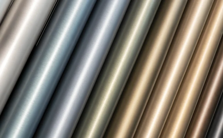
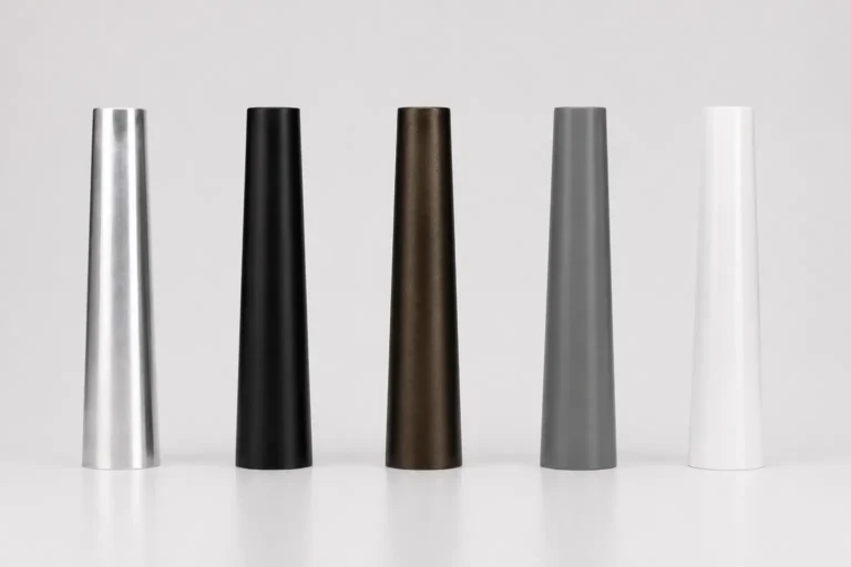

Natural aluminum; anodizing: 20 µm standard, available range 15–25 µm.

Most requested for urban and architectural projects

Fine texture, hides dust and handling marks

Standard municipal specification in EU tenders

Parks, resorts, pedestrian zones
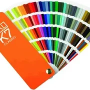
Available in the full RAL color range
Unequal arm loads must be engineered as one complete system
A high-and-low-arm pole carries two loads at different elevations and distances from the shaft. The shaft, connections and base must therefore be checked as a complete structural assembly.
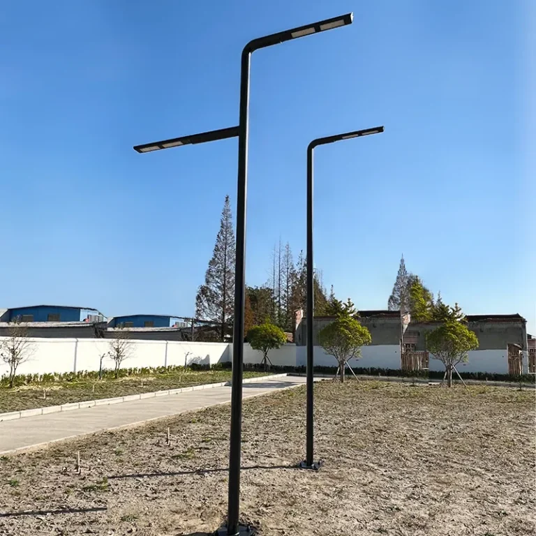
Independently positioned arms
Each arm connection is located according to its approved mounting height and orientation.
Load-aware reinforcement
Local reinforcement is added where required because the two arms transfer different bending moments into the shaft.
Protected cable branches
Internal wiring divides toward each luminaire through deburred and protected cable paths.
Controlled arm alignment
Outreach, tilt and rotational orientation are checked during trial assembly before finishing.
Reinforced base assembly
The base plate and gussets are sized using the combined effect of the shaft, both arms and both luminaires.
Configure each lighting level for its own target area
The high arm normally serves the primary roadway. The lower arm can be directed toward a pavement, cycle lane, side road, entrance or landscaped area. Height, outreach, tilt and orientation can be specified independently.
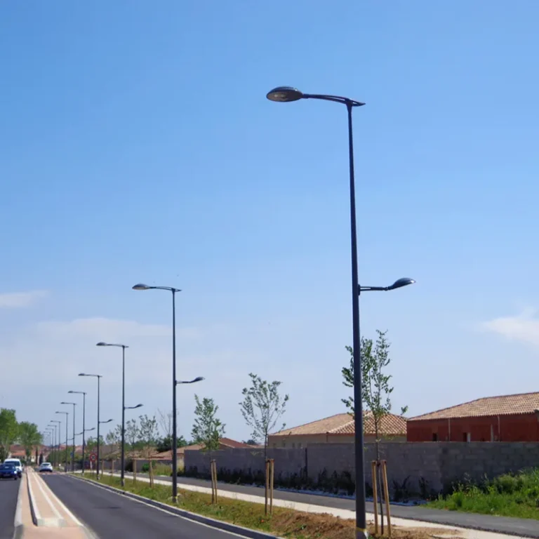
High long arm + low short arm
Separate mounting heights and optics
Different outreach on each arm
Wide-area high light + controlled low light
90°, 120°, 180° or project-specific orientation to approved drawing
One pole for the roadway and the space beside it
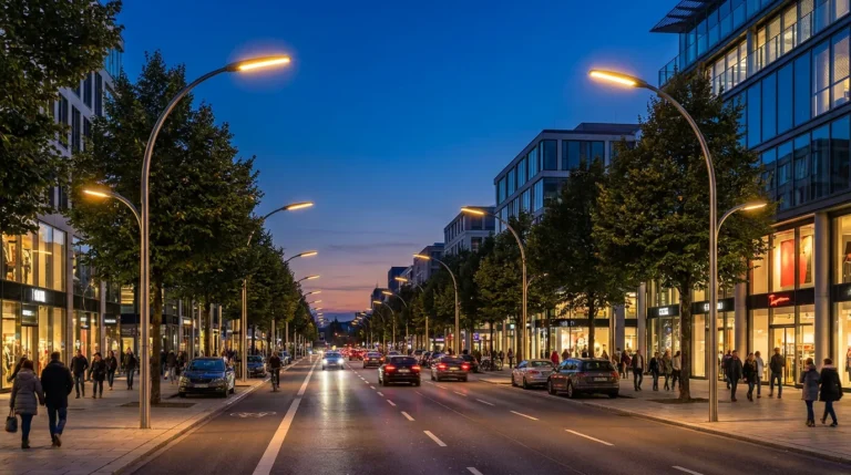
Urban road and footpath
High roadway arm with a lower pedestrian arm
Central road medians
8–10 m · 1.5–2.0 m per side
Cycle lane corridor
Roadway arm plus dedicated cycle-lane luminaire
Campus road
Vehicle lighting and pedestrian lighting from one pole
Car park perimeter
Parking-area coverage plus walkway lighting
Industrial roads
9–12 m · engineered configuration
Two adjacent zones, one coordinated pole
Each luminaire is positioned for its own target area without duplicating the foundation.
Two lighting levels, one pole and one foundation
Roads, paths and service lanes rarely require the same mounting height or light distribution. The YLDG-G Series places each luminaire at the height and outreach appropriate to its target zone.
Separate lighting planes
The high arm provides wider roadway coverage while the lower arm directs light toward an adjacent zone.
One shared foundation
Both luminaires use one shaft, one base plate and one underground cable-entry location.
Complete twin-luminaire calculation
The shaft, two arms and both luminaires are reviewed as one structural system using the combined weight and projected area.
Reduced pole count
Combining roadway and pedestrian lighting may eliminate a separate pathway pole where the layout permits.
Fewer foundations and cable points
One pole can serve two lighting directions, helping reduce foundations, trench connections and installation work on suitable layouts.
Matched architectural finish
Shaft and both arms are finished in the same production batch for consistent colour and gloss.
A pole factory, not a trading company
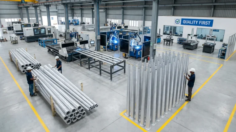
YUANTAI LIGHTING manufactures aluminum poles for municipal roads, commercial developments, campuses, landscape projects and lighting contractors.
High-and-low-arm poles are produced according to approved drawings. The mounting height, outreach, tilt and orientation of each arm are defined before production and checked during trial assembly.
OEM and ODM services are available. Custom drawings, finishes, identification labels, packaging and inspection documentation can be supplied according to order requirements.
Quality system
Environmental
EN 40 conformity
Material report
Manufactured and inspected as one matched three-part assembly
The shaft, high arm and low arm are produced against one approved drawing. Their mounting positions and orientation are checked together before finishing and packing.
Aluminum material, temper and wall thickness are checked against the order specification.
The shaft is formed to the specified taper and inspected for straightness.
Solution treatment and artificial ageing achieve the specified aluminum temper.
Mounting interfaces and local reinforcement are completed according to the approved drawing.
5. Flange and collar welding
Arm flanges, reinforcement collars, base plate and gussets are welded and inspected.
6. Surface treatment
The shaft and arms are anodized or powder-coated as one matched batch.
7. Final inspection
Dimensions, finish, accessories and identification marks are checked before packing.
Detachable arms reduce shipping volume and impact risk
High and low arms can be protected and packed separately from the main shaft, avoiding large projecting sections during container loading and international transport.
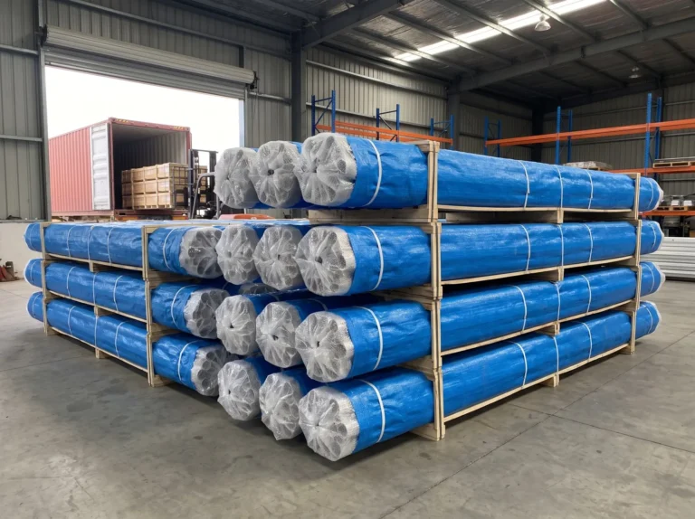
Each shaft is wrapped in pearl cotton and woven polypropylene so finished surfaces do not touch.
Arms nest in protected cartons with the connection faces covered. Every arm is identified by side and matched to its shaft.
Shafts are nested head-to-tail in fumigated timber frames with forklift access and steel strapping.
~100 pcs
~200 pcs
15–25 working days after deposit and drawing approval
Container quantities depend on pole height, arm configuration and packing method. A loading plan is prepared after the final production drawing is approved.
Questions buyers ask before ordering
A standard double-arm pole normally places two arms at the same height. A high-and-low-arm pole places the luminaires at different mounting levels for different target areas.
The higher arm commonly serves the roadway. The lower arm commonly serves a footpath, cycle lane, service road, entrance or landscaped zone.
Yes. They can face the same direction, opposite directions or a project-specified included angle, subject to structural review.
Yes. Outreach and tilt can be specified independently for each arm according to the lighting calculation.
Yes. Separate internal circuits can be provided so roadway and pedestrian luminaires can be controlled independently.
Provide pole height, both arm mounting heights, outreach, luminaire weights, projected areas, design wind speed and required standard.
Yes. Send the road width, adjacent-zone position and required luminaire coordinates for production-drawing review.
Yes. Factory inspection, third-party inspection and pre-shipment photo documentation can be arranged.
Add the road-section drawing, luminaire weight, projected area and design wind speed for a more accurate configuration and structural review.