

Aluminum Curved Light Pole, 4–12 m
- YLDG-H Series
- 6063-T6 aluminum construction with a continuous swept profile
- Standard 5 m–10 m heights with custom reach and curve geometry
- Project-specific review for fixture load, EPA and wind conditions
| MOQ | 10 sets; mixed standard heights accepted |
|---|---|
| Standard height | 4–12 m standard; custom heights up to 15 m subject to structural review |
| Curved reach | 1.5 m / 1.8 m / 2.0 m standard; custom geometry available |
| Curve profile | Continuous swept curve developed from the approved drawing |
| Material | Aluminum alloy 6063-T6; alternative alloy subject to review |
| Finish | Mill / Anodized / Powder Coated / PVDF |
| Installation | Anchor-base flange; other methods available on request |
| Lead time | 15–25 working days after deposit and drawing approval |
| Port | Ningbo / Shanghai · FOB, CIF and DDP available |
Manufacturing Aluminum poles for export markets
Own factory with spinning, welding & coating lines
Annual capacity across 3 production lines
Exported to EU, North America, Middle East, SEA
Technical Specifications
Reference specifications for curved aluminum light poles. Final height, curved reach, profile geometry, shaft dimensions, finish and foundation requirements are confirmed against the approved project drawing and structural calculation.
| Model | YLDG-H Series |
|---|---|
| Product type | Aluminum curved lighting pole |
| Material | Aluminum alloy 6063-T6; alternative alloy optional |
| Standard height | 5,000 – 10,000 mm |
| Profile | Continuous single-direction curved upper section |
| Standard reach | 1,500 / 1,800 / 2,000 mm |
| Curve height H2 | 1,000 / 1,200 / 1,500 mm |
| Top outside diameter | 76 mm standard |
| Base outside diameter | 152 – 200 mm |
| Standard wall thickness | 4.0 mm |
| Cable routing | Concealed internal cable route |
| Access door | Reinforced lockable aluminum cover |
| Door height | 500 mm above base in standard configurations |
| Base plate | Aluminum flange sized to project load |
| Anchor assembly | Galvanized anchor bolts with positioning template |
| Installation | Anchor-base flange; custom installation available |
| Surface treatment | Anodizing / polyester powder coating / PVDF |
|---|---|
| Colour | Natural aluminum or any project-specified RAL colour |
| Finish thickness | Powder coating: 80 µm standard; available range: 80–120 µm. Anodizing: 20 µm standard; available range: 15–25 µm. |
| Pre-treatment | Cleaning, etching and conversion treatment appropriate to finish |
| Corrosion protection | Selected for inland, coastal or industrial exposure |
| Wind resistance | Calculated from project wind speed and installed equipment |
| Design reference | EN 40 / AASHTO / applicable local standard |
| Fixture load | Confirmed from weight, projected area and curved reach |
| Electrical route | Internal cable route from access door to pole top |
| Earthing | Internal earth connection point |
| Inspection | Dimensions, curve geometry, welding and finish inspection |
| Service life | Dependent on environment, specification and maintenance |
| Documentation | Production drawing and inspection records available |
| Custom engineering | Structural review available for project configurations |
Standard Sizes of Aluminum Curved Light Pole
| MODEL M | HEIGHT H | TOP OD D1 | BASE OD D2 | THICK T | ARM L1 | HEIGHT2 H2 | DOOR HEIGHT H1 | DOOR SIZE (A×B) | BASE SIZE (L×W×T) |
|---|---|---|---|---|---|---|---|---|---|
| YLDG-H1 | 5000 | 76 | 152 | 4.0 | 1500 | 1000 | 500 | 80 × 250 | 298 × 298 × 12 |
| YLDG-H2 | 6000 | 76 | 152 | 4.0 | 1500 | 1000 | 500 | 80 × 250 | 298 × 298 × 12 |
| YLDG-H3 | 7000 | 76 | 166 | 4.0 | 1800 | 1200 | 500 | 80 × 250 | 298 × 298 × 12 |
| YLDG-H4 | 8000 | 76 | 180 | 4.0 | 1800 | 1200 | 500 | 100 × 300 | 305 × 305 × 19 |
| YLDG-H5 | 9000 | 76 | 180 | 4.0 | 2000 | 1500 | 500 | 100 × 300 | 305 × 305 × 19 |
| YLDG-H6 | 10000 | 76 | 200 | 4.0 | 2000 | 1500 | 500 | 100 × 300 | 305 × 305 × 19 |
Five stock finishes, any RAL to order
The complete curved surface is prepared and finished as one coordinated component, maintaining consistent colour, gloss and coating thickness through the transition area. Finish thickness: Powder coating: 80 µm standard; available range: 80–120 µm. Anodizing: 20 µm standard; available range: 15–25 µm.
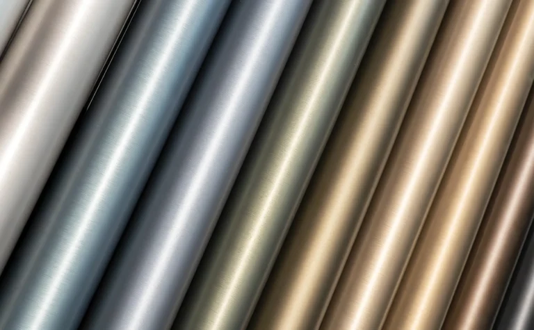
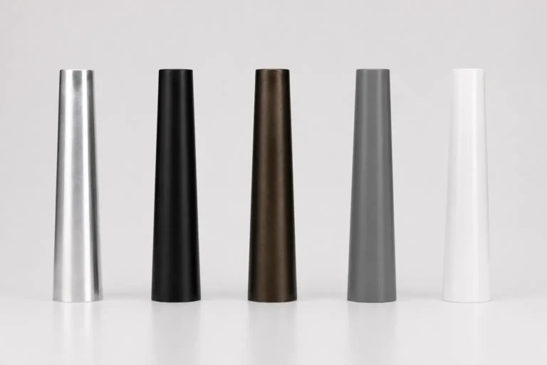

Natural aluminum; anodizing: 20 µm standard, available range 15–25 µm.

Most requested for urban and architectural projects

Fine texture, hides dust and handling marks

Standard municipal specification in EU tenders

Parks, resorts, pedestrian zones
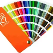
Available in the full RAL color range
The curve must control both appearance and structural load
A curved lighting pole carries the fixture away from the shaft centreline, creating a permanent cantilever moment. Reliable performance depends on controlled curve geometry, consistent wall thickness and a base assembly designed for the resulting load.
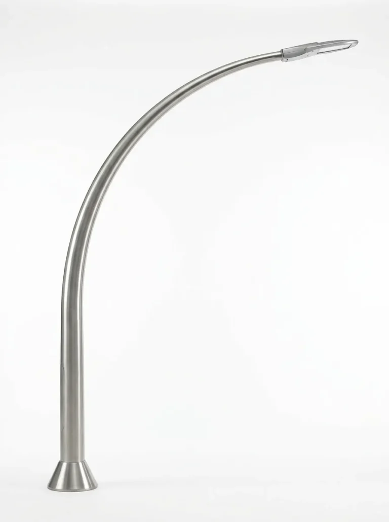
Controlled curve geometry
The upper profile is checked for reach, curve height, radius and fixture position against the approved drawing.
Smooth transition zone
The vertical shaft develops gradually into the curved section without an abrupt visual or structural discontinuity.
Cantilever-load review
Fixture weight and wind area act away from the shaft centreline and are included in the structural review.
Reinforced access opening
The maintenance door is positioned above the base and reinforced for safe service access.
Load-spreading base
The base flange, gussets and anchors distribute bending forces into the foundation.
Control reach, height and curvature independently
The character of the pole is defined by overall height, horizontal reach and the height over which the curve develops. Adjusting these dimensions changes both the appearance and the light position.
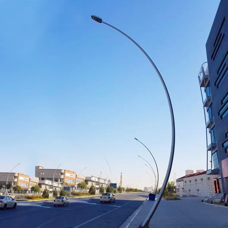
Short, restrained upper curve for paths, courtyards and smaller commercial spaces.
Balanced reach and height for residential streets, campuses and car parks.
Increased reach for wider roads, entrances and setback installations.
Custom radius and proportions developed from the architect’s elevation.
Jig-controlled geometry for consistent appearance across large quantities.
Where these poles are installed
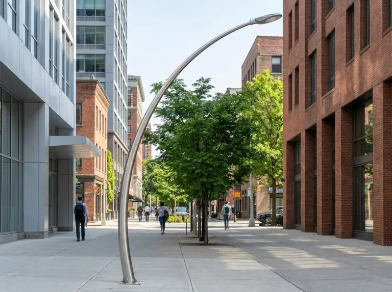
Urban boulevards
8–10 m poles with extended reach for coordinated roadway lighting.
Residential streets
6–8 m configurations with a balanced standard curve.
Parks and pathways
Compact architectural profiles for pedestrian and landscape areas.
Commercial entrances
Custom curve geometry and colour for branded developments.
Campuses
A consistent, recognizable profile across roads and shared spaces.
Resorts and hotels
Decorative finishes and softer proportions for hospitality landscapes.
Waterfront projects
Exposure-specific aluminum finish systems for humid environments.
A lighting structure designed as part of the architecture
The curved pole replaces the abrupt transition between a vertical shaft and a conventional bracket with one coordinated visual line. It positions the light over the required area while giving roads, parks and commercial developments a recognizable identity.
Continuous visual profile
A sweeping upper curve creates a cleaner silhouette than a straight pole with a separate bracket.
Project-defined light position
Height, reach and curve geometry are developed from the lighting layout.
Smooth structural transition
The gradual profile avoids an abrupt change in direction and supports controlled load transfer.
Lighter site handling
Aluminum construction simplifies lifting, positioning and installation.
Low-maintenance surface
Anodized and coated finishes are available for inland, coastal and architectural environments.
Custom architectural identity
Coordinate curve, height, reach and colour with the project’s design language.
A pole factory, not a trading company
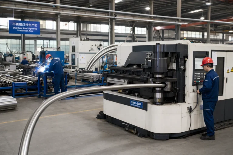
Founded in 2003, we operate a 50,000 m² light-pole manufacturing plant with dedicated forming, welding and surface-finishing capabilities. Annual output is approximately 120,000 poles.
We supply lighting contractors, distributors and project buyers across Europe, North America, the Middle East and Southeast Asia. Curved aluminum poles can be produced to customer drawings with OEM branding, custom geometry, finishes and project-specific packing.
Our engineering team reviews height, curved reach, profile geometry, fixture weight, projected area, design wind speed and foundation requirements before production.
Quality system
Environmental
EN 40 conformity
Material report
From aluminum material to a controlled curved profile
Curved poles require more than standard length and diameter checks. Each pole is compared with the approved profile so the reach, transition height and visual line remain consistent across the project.
Confirm height, reach, curve geometry, fixture data, wind conditions and installation method.
Check aluminum grade, dimensions and documentation against the approved specification.
Prepare the shaft and verify wall thickness, diameter and straightness.
Form the upper profile using controlled tooling based on the approved drawing.
05 · Base fabrication
Complete the flange, gussets, access opening and internal electrical provisions.
06 · Geometry inspection
Check overall height, reach, curve radius, transition height and fixture position.
07 · Finish, QC and packing
Apply the approved finish, complete dimensional checks and protect the pole for shipment.
The curved section receives additional protection
Unlike a straight pole, a curved pole cannot always be nested uniformly. Packaging protects the projecting upper section and prevents the finished curve from contacting adjacent poles during transport.
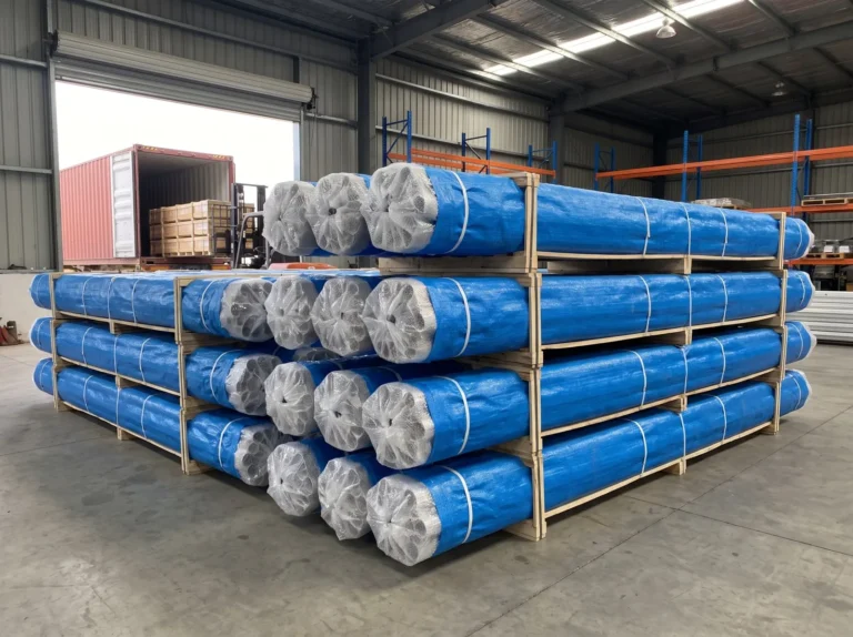
Non-abrasive wrapping protects the complete finished pole.
Additional cushioning is applied around the curved transition and upper end.
Spacers prevent projecting sections from touching adjacent poles in transit.
Anchor sets, access covers and hardware are packed and labelled for each batch.
Timber or project-specific supports stabilize the non-linear pole profile.
Container arrangement is calculated from height, reach, curve direction and order mix.
Container quantities depend on pole height, curved reach, whether different sizes are mixed and the required packing method. A loading estimate is issued after the final drawings are approved.
Questions buyers ask before ordering
A single-arm pole uses a separate bracket on a vertical shaft. A curved pole uses a sweeping profile to position the fixture with a more integrated architectural appearance.
No. A davit normally has a shorter localized bend near the top; this curved form develops over a larger section of the structure.
Yes. Height, reach, curve height and radius can be developed from the project drawing and reviewed structurally.
Provide location, wind speed, terrain category, height, reach, fixture weight, projected area and installation method.
Yes. The approved profile is transferred to production fixtures and inspection templates for repeatability.
The finish is selected from salt exposure, humidity, distance from the coast and maintenance conditions.
Yes. Send a PDF, DWG, elevation or reference sketch for manufacturability review and production drawing approval.
Yes. Factory or third-party inspection can be arranged, with dimensional, finish and packing records available.
Include the overall height, horizontal reach, curve height or reference drawing, fixture weight, projected area, design wind speed, quantity, finish and installation location. We will review the configuration and prepare a quotation with a production drawing.