
Aluminum Direct Burial Light Pole
- YLDG-DB Series
- Seamless spun-tapered 6063-T6 aluminum shaft
- No base plate or anchor-bolt cage required
- Embedment engineered for project soil, wind and equipment loads
| MOQ | 10 sets (mixed heights and finishes accepted) |
|---|---|
| Above-ground height | 4 m / 5 m / 6 m / 8 m / 10 m / 12 m — custom available |
| Embedment depth | Typically 0.8–2.0 m, confirmed by foundation design |
| Installation | Direct burial in concrete or approved engineered backfill |
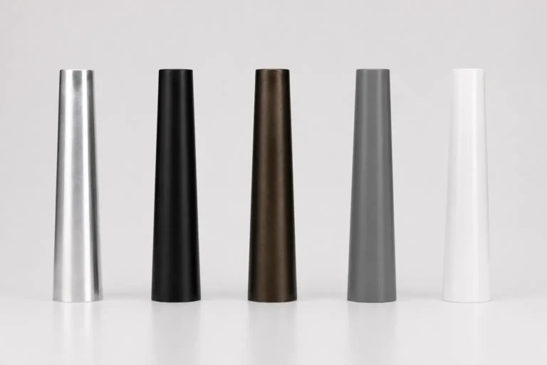
| Finish | Mill / Anodized · Matte Black · Bronze · Matte Grey · Gloss White |
| Lead time | 15–25 working days after deposit and drawing approval |
| Port | Ningbo / Shanghai · FOB, CIF and DDP available |
Manufacturing aluminum poles for export markets
Own factory with spinning, welding & coating lines
Annual capacity across 3 production lines
Exported to EU, North America, Middle East, SEA
Technical Specifications
Standard manufacturing capabilities for the YLDG-DB Series. Final shaft dimensions, embedment depth and foundation requirements must be confirmed against the approved project drawing and structural calculation.
| Model | YLDG-DB Series |
|---|---|
| Shaft material | Aluminum alloy 6063-T6; 6061-T6 optional |
| Forming process | CNC spinning, seamless conical taper |
| Cross-section | Round tapered; octagonal optional |
| Above-ground height | 4–12 m; custom heights available |
| Overall pole length | Above-ground height plus embedded section |
| Wall thickness | 2.5 / 3.0 / 3.5 / 4.0 / 5.0 mm |
| Embedment depth | Typically 0.8–2.0 m, subject to foundation design |
| Embedded section | Integral extension of the aluminum shaft |
| Cable entry | Deburred below-grade slot; position customized |
| Hand hole | Reinforced opening with lockable aluminum cover |
| Base plate / anchor bolts | Not required |
| Surface treatment | Powder coating / anodizing / PVDF fluorocarbon |
|---|---|
| Finish thickness | Powder coating: 80 µm standard; available range: 80–120 µm. Anodizing: 20 µm standard; available range: 15–25 µm. |
| Colour | Any RAL; standard options RAL 7016, RAL 9005, RAL 9016 and bronze |
| Ground-line protection | Reinforced coating, protective sleeve or project-specific barrier |
| Wind resistance | Calculated from height, equipment load and project wind speed |
| Design standards | EN 40 / AASHTO LTS / applicable local standards |
| Certification | ISO 9001, ISO 14001, CE and material reports where applicable |
| Earthing | Internal earth stud with copper lug |
| Cable route | Internal cable path through the shaft |
| Installation | Direct burial in a project-designed foundation |
Standard Sizes of Aluminum Direct Burial Light Pole
| Model | Above-ground height | Embedment | Overall length | Top Ø | Ground-line Ø | Wall | Hand-hole height |
|---|---|---|---|---|---|---|---|
| YLDG-DB1 | 4,000 mm | 800 mm | 4,800 mm | 60 mm | 125 mm | 2.5 mm | 500 mm |
| YLDG-DB2 | 5,000 mm | 1,000 mm | 6,000 mm | 60 mm | 140 mm | 3.0 mm | 500 mm |
| YLDG-DB3 | 6,000 mm | 1,200 mm | 7,200 mm | 76 mm | 155 mm | 3.0 mm | 500 mm |
| YLDG-DB4 | 8,000 mm | 1,500 mm | 9,500 mm | 76 mm | 185 mm | 3.5 mm | 500 mm |
| YLDG-DB5 | 9,000 mm | 1,600 mm | 10,600 mm | 76 mm | 200 mm | 3.5 mm | 500 mm |
| YLDG-DB6 | 10,000 mm | 1,800 mm | 11,800 mm | 90 mm | 220 mm | 4.0 mm | 500 mm |
| YLDG-DB7 | 12,000 mm | 2,000 mm | 14,000 mm | 90 mm | 250 mm | 5.0 mm | 500 mm |
Catalogue values are for preliminary selection. Final embedment and foundation design depend on soil, groundwater, frost depth, wind speed and equipment loads.
Five stock finishes, any RAL to order
The visible shaft can be supplied in a mill, anodized or powder-coated finish. The buried section and ground-line transition can receive additional protection according to soil moisture, salinity and chemical exposure. Finish thickness: Powder coating: 80 µm standard; available range: 80–120 µm. Anodizing: 20 µm standard; available range: 15–25 µm.
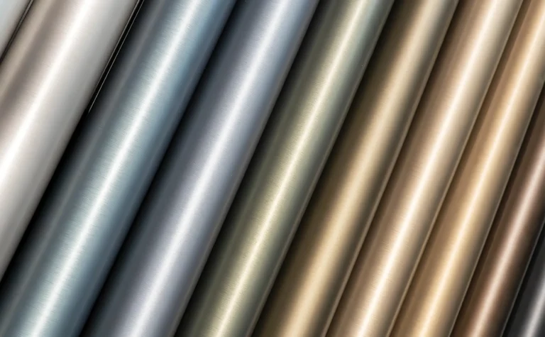

Natural aluminum; anodizing: 20 µm standard, available range 15–25 µm.

Most requested for urban and architectural projects

Fine texture, hides dust and handling marks

Standard municipal specification in EU tenders

Parks, resorts, pedestrian zones
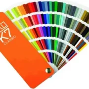
Available in the full RAL color range
Direct burial performance depends on the ground-line transition
The most critical area is where the shaft passes from air into soil or concrete. Moisture, salts and surface damage concentrate at this transition, so the embedded section, cable entry and ground-line protection must be detailed for the actual site.
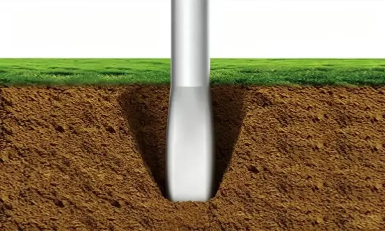
Integral embedded shaft
The buried section is formed as part of the pole, avoiding an additional structural joint near the foundation.
Ground-line protection
Enhanced coating or a protective sleeve can extend above and below grade to protect the highest-exposure transition zone.
Smooth cable entry
The underground cable opening is cut to the approved position, deburred and radiused to protect cables during pulling.
Reinforced hand hole
The access opening is strengthened to recover local stiffness and supplied with a secure weather-resistant cover.
Drainage-aware installation
Foundation detailing can include drainage material or other approved measures to avoid trapping water around the embedded shaft.
Match the embedded section to the site—not just the pole height
Two projects using the same 8 m pole may require different burial depths because wind load, soil strength, groundwater, frost depth and equipment area are different. We configure the embedded section from the approved project data.
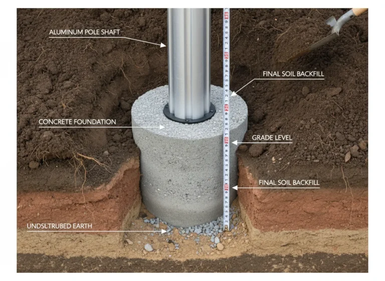
For roads, car parks and industrial sites with stable soil and a project-designed concrete foundation.
Additional embedded length for soft ground or increased overturning demand, subject to structural review.
Reinforced coating or a protective sleeve for wet, coastal or chemically aggressive soil.
Foundation detailing that reduces trapped water around the embedded shaft.
Factory-positioned entry slots align with the approved underground conduit layout.
Where these poles are installed

Municipal roads, utility projects and clean public spaces
Direct burial poles simplify foundation hardware and provide a clean ground-level appearance for roads, car parks, parks and infrastructure sites.
Municipal roads
6–10 m · project-specific embedment
Residential streets
5–8 m · clean ground-level installation
Car parks
6–10 m · simplified foundation hardware
Parks & pathways
4–6 m · unobtrusive base detail
Utility & infrastructure sites
6–12 m · engineered foundation
Coastal developments
Project-specific ground-line protection
Faster installation without anchor bolts or base plates
The extended shaft is installed directly into the foundation, removing the flange, anchor cage and bolt-alignment process. It is a practical solution when simple foundations, clean ground-level appearance and rapid installation are priorities.
No exposed base hardware
With no flange, nuts or base cover, the shaft meets the finished surface with a clean, uncluttered appearance.
Project-specific embedment
Burial depth and shaft dimensions are selected from pole height, equipment load, wind speed, groundwater and soil conditions.
No anchor-bolt cage
The extended shaft installs directly into the foundation, eliminating the base plate, anchor bolts and template-alignment stage.
Faster site installation
Contractors position, plumb and cast the pole without a separate anchor-cage alignment stage.
Flexible cable entry
Factory-cut cable slots are positioned below ground and finished with smooth edges for the incoming power conduit.
Protected below-grade section
The embedded and ground-line areas can receive enhanced coating or a protective sleeve for aggressive soil.
A pole factory, not a trading company
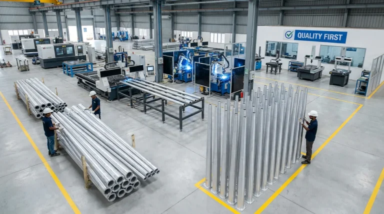
Founded in 2003, we operate a 50,000 m² light-pole manufacturing plant with aluminum spinning, heat-treatment, machining and surface-finishing capabilities. Annual output is approximately 120,000 poles.
We supply lighting contractors, distributors and project buyers across Europe, North America, the Middle East and Southeast Asia. Direct burial poles can be produced to customer drawings with custom embedment, cable-entry positions, finishes and OEM packaging.
Our engineering team reviews above-ground height, soil information, wind speed, equipment weight, projected area and foundation requirements before production.
Quality system
Environmental
EN 40 conformity
Material report
Built as one continuous shaft from top to embedded base
The complete pole—including its burial section—is formed, inspected and finished as one matched component. Cable openings and protection zones are positioned from the approved foundation drawing.
Aluminum tube is checked against the material certificate and production specification.
The tube is formed into a continuous conical profile with the required overall length.
The formed shaft is processed to achieve the specified alloy temper.
Hand holes and underground cable-entry slots are cut, deburred and reinforced.
5. Straightness inspection
Overall length, taper, diameter and shaft straightness are checked.
6. Protection-zone application
Specified ground-line and below-grade protection is applied after surface preparation.
7. Final inspection and packing
Dimensions, finish and accessories are verified before protective wrapping.
Protected along the full length—including the embedded section
Direct burial poles are longer than their nominal mounting height, so packaging and container planning are based on overall pole length. Extra wrapping protects the ground-line transition and below-grade coating during transport.
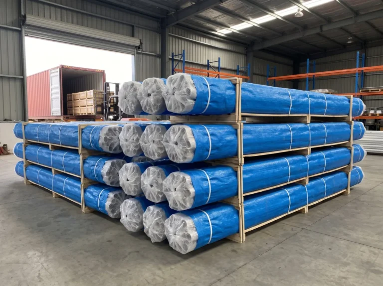
Each pole is wrapped in foam and woven material to protect the visible and embedded sections.
Additional wrapping protects the transition zone and below-grade coating from handling damage during loading and transport.
Tapered shafts are nested head-to-tail in reinforced, forklift-ready bundles.
~100 pcs
~200 pcs
15–25 working days after deposit and drawing approval
Loading quantity depends on overall pole length, maximum shaft diameter and nesting ratio. A detailed loading plan is supplied with the quotation.
Questions buyers ask before ordering
Embedment cannot be selected from height alone. It depends on wind load, equipment area, soil strength, groundwater, frost depth and local standards.
Most projects use a designed concrete foundation. Alternative engineered backfill systems may be possible when accepted by the local authority and foundation engineer.
Yes. Send the pole schedule, soil information, foundation drawing and cable-entry requirements, and we will configure the embedded section for approval.
A direct burial pole extends into the foundation and uses no base plate or anchor cage. An anchor-base pole is bolted to embedded anchors and can be removed without excavation.
Additional coating or a ground-line sleeve can be specified for wet, saline or chemically aggressive soil.
Yes, but replacement normally requires excavation or partial foundation removal. Choose an anchor-base pole when easy future removal is essential.
A factory-cut, deburred cable-entry slot is positioned below finished ground to align with the site conduit. Cables then run internally through the shaft.
Yes. Mixed heights, finishes and cable-entry positions can normally be included within the minimum order quantity, subject to production confirmation.
Include the above-ground height, equipment weight and projected area, soil condition and cable-entry position. We will recommend the shaft dimensions, embedded length and protection system.